Programming graphics for Sharp LL-151-3D parallax barrier auto stereoscopic screens
1. Introduction
About a year ago I got asked if I could provide stereographic output suitable for a single person 3D screen (if I remember it correct it was the Sharp LL-151-3D, but I may be wrong) from one of my programs. As I was programming under Linux, and using CUDA with OpenGL for rendering I needed to figure out how to address the screen. I was not able to dig out any direct description how it worked on the Internet, and thus had to figure it out myself.
Afterwards I thought that I should write up a simple example program and post here, but time ran away and I got other things to do. Recently I saw a question about this problem posted somewhere else and remembered what I wanted to do. I do not any longer have access to the screen and thus can not test an example program for correctness, so I will just describe how to combine a stereo pair for the screen, and give the algorithm. Most graphics programmers in the need of the solution should be able to take it from there.
2. Background
An autostereoscopic monitor gives the viewer a three dimensional viewing experience without the need of any special glasses, just by looking at the screen. It achieve this by making sure that separate images are viewed by the observer's left and right eyes. One technical solution for this is to use parallax barriers .
The basic principle is that a set of vertical barriers is located in front of the LCD to block view of more than one image from certain directions. An introduction can be found here.
Exactly how this works does not matter in the following, but it allows for two different images to be visible at two different positions in space; corresponding to the left and right eye of an observer. If these images consists of a stereo pair a three dimensional image is perceived. So in other words: the screen make sure that the frame buffer image sent to it is somehow split up to two different image that is mutually exclusively visible from two different positions in space.
The problem is to figure out what screen data goes to the left image and what data goes to the right.
The Sharp screen, like (most) other 3D monitors is addressed through a normal VGA/DVI port, just like normal screens. This means that once you connect it to your graphics card you have to figure out a way to combine your two images so that the monitor correctly show them. On expensive workstation graphics cards, such as the Nvidia Quadra series, the driver can automatically perform this for example using the OpenGL stereo buffer. However, today's cheaper "gaming" graphics cards should have that functionality although I guess it is not present in the driver. (At least it wasn't under Linux when I tried.) I was using a GeForce 9800GT as I recall, but you should be able to program this on any card with a pixel/fragment shader. So, in order to program our card to send the correct image for stereo-viewing we need to figure out how it interprets the data. Combining several series of data (two images in our case) into a single series (one image) is called multiplexing .
There are two different basic ways we can perform multiplexing for the Sharp screen: in time and in space (or well frequency, but I will call it space here). If the Sharp screen worked by time multiplexing it would accept every second image as the right eye image and every second as the left eye image and then combine them into a single image (or show every second somehow, this is how shutter glasses work by the way).
This kind of screen works by spatial multiplexing though. (I figured this out by implementing the method below and testing. However, it was a fairly safe bet as the barriers themselves divide the resolution of the screen.) So the left and right eye images must be combined into a single image in the frame buffer of the graphics card.
3. Screen image format
There are of course a great number of different ways to take data from two RGB images and combine them into a single one. The simplest is probably to put the left image in the left half and the right image in the right half. However, considering that the parallax barriers are thin vertical strips over the entire LCD this would require the screen hardware to rearrange the data i an extra processing step. Thus this seem unlikely. Rather, it would make sense for the monitor to require the image in a ready-to-display format. Thus, in the exact striped pattern as the parallax barrier. Following this, it would make sense to try to take the first pixel column from the left eye image, the second from the right eye image, the third from the left again, and so on. If one does this however the result is not a stereoscopic image, but rather a striped, blurry version with offset colors. Clearly something is wrong with this approach. This is the stage where I have seen some experiments at before. The screen does seem to display a different image for each eye, but not the correct one. And what is up with the colors?
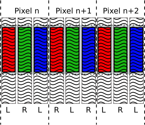
Focusing on that last question will let us solve the problem. Most color LCD screens has a separate sub-pixel, or element, for each red, green, and blue component. See for example Wikipeda and the lower right part of Fig. 1.
A layout like this would create a RGB columns. What if the parallax barriers blocks color channels in stead of whole pixels? This would actually benefit the smoothness of the whole image by making the 'jumps' between barriers smaller. So, is it possible to have barriers arranged over the individual color channels and still manage to have the right red, green, and blue values to show simultaneously for each image?
3.1. The solution
It turns out the the answer to that question is yes, and this is also the solution. Consider a barrier pattern of the same size as the color elements. Fig. 2 shows a part of a screen line. The color elements repeats: red, green, blue; red, green, blue; with three elements making up a screen pixel. However, the left and right barriers alternate per element (and not per pixel) as indicated by the pattern overlays and the L and R labels in the image. Now, let us have a look at what information are sifted out by the two different barriers, as shown in Fig. 3.
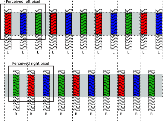
Note that in Fig. 3 that the barrier separate every second color element into the left image and every second into the right image. The resulting images still have periodic red, green, and blue triplets that may be interpreted as pixels. The boxes in Fig. 3 denotes the a perceived left and right image pixel. (It is larger than the screen pixel, but that is only natural as we multiplex two images in the screen image.)
As can be seen, the triplets' color elements are permuted internally so that the left image has a red, blue, green order and the right one a green, red, blue order. This does not matter however. The perceived color of a pixel is the combined contributions from each of the color components. (This is why all the different pixel geometries shown in Fig. 1 works and all gives the same colors.) What matters is that one element of each base color lies next to each other.
This layout explain why we can not simply take every second pixel in the screen image from every second of the two images we want to multiplex. Each screen pixel gets chopped up so that two of its color elements go to one of the perceived images and one to the other. Thus any perceived pixel will have one wrong color component (and thus also intensity) contribution. This should lead to somewhat blurred image with a color offset, which is exactly what the every second pixel experiment showed.
Now, instead what we need to do when combining the images is exactly the inverse process of Fig. 3: for each pixel on screen we take two color components from one image and one from the other. For the next screen pixel we take the single remaining component from the first image pixel and the two remaining components from the second image pixel, and so on. The algorithm below outlines how to combine two images using this method.
  Input: fullScreenWidth, fullScreenHeight // Size of the
                                           // full screen framebuffer
  Input: LeftImage, RightImage // Image arrays of size
                               // fullScreenWidth /2 , fullScreenHeight
  Output: FrameBuffer // Image of size fullScreenWidth, fullScreenHeight

  for y = 0 to fullScreenHeight -1
   for x = 0 to fullScreenWidth -1
     if(x is even) then
        FrameBuffer[x,y] = RGB( LeftImage[x/2,y].red,
                                RightImage[x/2,y].green,
                                LeftImage[x/2,y].blue);
      else
        FrameBuffer[x,y] = RGB(RightImage[x/2,y].red,
                               LeftImage[x/2,y].green,
                               RightImage[x/2,y].blue);
      end if;
    end for;
  end for;
The above algorithm should multiplex the two images correctly so that if a stereo pair is used as input the resulting perceived image from the Sharp screen (with 3D turned on) is indeed a 3D image. As I stated in the introduction, I am not able to provide any screen shots or code from my own experiments, but this is anyway how it works.
Let me know if you spot any errors in the text, and if anyone with this screen implements a program after reading this it would be fun to know that it worked out for you as well.
.L